Before starting, I needed to formalize motivation + a proper plan of action.
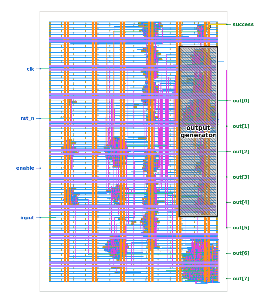
Jane Street recently released the physical/geometric layout of a small ASIC chip, and asked us to reverse-engineer what it does. I had recently failed to solve their neural network reverse engineering task, so thought I would give this a go. By most framings, this was a deeply irresponsible use of time, but the only reason I was able to complete something of this magnitude / complexity is because of a deeper motivation: mech interp - I think this is a very mech-interp-pilled task. The ability to understand complex hierarchical systems, objects, collectives, has always been very valuable, but is going to become exponentially more valuable pre-singularity.
Details below, but TLDR:
I began with raw provided GDS geometry and worked towards a standard-cell netlist (as they advised). From there, I built a sequential model and used this to get to a constraint system which could be SAT-solved. With any complex object, there are multiple 'stories' that can capture its details: different/disjoint explanations that nonetheless accurately represent the underlying truth. My overarching question was always 'is this the right abstraction / level of abstraction', and 'how can I prove to myself that it is'. To try force this:
- The extracted connectivity had to reproduce the provided adder chip
- The recovered logic had to match the supplied traces (eg: given this chip input, this is the output)
- The solver result had to pass the complete gate-level model
- Etc.
I've tried to keep this read as first-principled as possible, but it is an inherently complex topic so please excuse jargon and message me if you need any more details - joshua.stapleton.ai@gmail.com. Prior to a few weeks ago, I knew ~nothing about chip design, and so excuse incorrect / wack terminology.
I've chosen to present my methodology at this interactive-blog level of abstraction, because providing the raw code I used would be like providing raw GDS geometry and asking someone to reverse engineer an ASIC from it ;)
Getting to a standardized netlist
Despite knowing this was likely a non-starter, I first tried to follow the circuit at transistor-level for funsies. This was very interesting, but I quickly found myself trying to understand how each gate works from first principles and realized this would be hard to scale.
Zooming in on the 3D view on GDS viewer felt deeply overwhelming, like I was a rat in New York:
I needed to go at least one level of abstraction up, and luckily Jane Street gave a hint here: the useful intermediate representation was the standard-cell netlist. The chip used the open SkyWater 130 nm library, so the metadata gave information on cell identity and where they were placed. The next step was therefore to recover the metal connections between named cell pins and use this to build a topologically-equivalent logic model.
I basically had all the nodes of the graph (the cells, and their different flavors) and now just had to figure out how they composed. My mental model here was like a cake - I knew the ingredients but needed to figure out how they were put together to get to the final baked good.
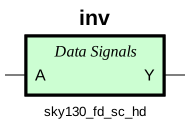
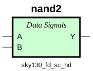
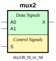
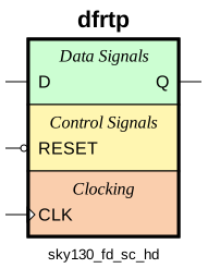
Known standard cells reduce the remaining task to connectivity recovery.
Extractor validation
I used gdstk to flatten + read the GDS, then Shapely to join all touching conductors on each routing layer (the via macros connected each of the layers.) The cell pin shapes from the Sky130 PDK attached those anonymous metal components back to their logical ports, and so I was able to see that the final Verilog held 738 logical total instances across 67 cell types (this gave me some hope: 67 is a reasonable number of ingredients). Also, I can't help but worry that 67 isn't coincidental. The interactive diagram below (which I encourage you to play with, it took forever to get right) uses placed pin data for these 728 routed instances.
I'm making this sound like it was easy - it definitely took some experimentation as connectivity errors can sneak in - eg: a complete-looking netlist can still have misplaced vias / an incorrect pin attachment may fail much much later. I used Jane Street’s worked adder (from the Github) as a stress-test: the extractor code had to recover the adder's exact connectivity, then reproduce the A + B = 496 result.
Here's the full interactive netlist and how it maps directly to the geometry. Getting to the netlist was incredibly useful - it represented a pretty clean leap up the abstraction mountain.
Hover either the physical or netlist view for cell details. Each graph node and physical outline shares the same extracted instance ID. Hover either pane to preview the one-to-one correspondence; click to hold a cell. The left and right edge labels are top-level ports. Inputs fan into connected sinks, while each output label marks its exact driver cell. Activity mode is illustrative; the validation replay below uses recovered signal values. Switch between cells, nets and illustrative activity; use the fixed zoom buttons and drag the graph to pan.
Validating the recovered logic
After playing around with the netlist, I was able to extract Boolean models using the Sky130 Liberty details, and simulated the resulting Verilog with Icarus. The supplied example attempts were a useful (second) validation target. Clock for clock, the rebuilt circuit emitted the same TRY AGAIN message.
One sub-network in the output block seemed useless, but JS already flagged this. To double-check, a backward dependency slice showed that this sub-network could not affect the final success, and four-state simulation with the official cell models showed that it could not change the final output. I therefore left it outside the success analysis + recorded it as an extraction limitation, but flagged it for the below easter-egg hunting!
In addition to having the netlist, I could see that the example input contained 121 bits. I give more details on the intuition behind this in the below diagram, but dividing the input into eleven 11-bit rows, noting seven bits per row least-significant-first as ASCII, and treating the remaining four as zero helped decode “The night s” and “ky awaits”. After some Googling, the 11 x 11 structure + night sky reference led me to Star Battle (and Jane Street had posted on it before):
Why 121 suggested an 11 x 11 grid
The interface took in 121 bits before checking the result; I know Jane Street is super mathy and loves hard puzzle games, so there had to be some significance to this number. Since 121 = 11 x 11 is square, a square board seemed like a natural structure to test, but I'd be lying if I didn't go down a number of rabbit-holes before getting here!
Choose the A/B attempt then click a numbered group and use the slider to inspect its eleven bits and decoded character.
TASCII 84My hypothesis became much stronger when each supplied attempt split cleanly into eleven 11-bit groups. In every group, seven low bits formed an ASCII character and four high bits were zero which is another give-away.
The two traces joined to read The night sky awaits. A square grid plus a direct reference to stars suggested Star Battle. I actually knew the game - but my version is called "Queens" - have it on my phone. The recovered success logic confirmed that we needed two ones per row, column and region, with no touching pair.
Choose an attempt, drag the clock slider to inspect any point, or replay all 121 input clocks.
The night sclock 121 / 121Together the two failed inputs say: The night sky awaits.
The chip is a streaming checker
The 121 bits are not stored as an all-in-one snapshot. They arrive row-by-row and update a small set of local memories (I flag these green cells in the above netlist diagram).
Overall, the strongest architectural clue was 11 + 11 + 1: eleven column counters, eleven region counters, and one row counter reused every eleven clocks. That arrangement is more specific than the numerical coincidence 121 = 11 x 11.
Luckily, adjacency needs very little history. A 13-bit window lets the current star check the four earlier positions that could touch it: one, ten, eleven and twelve clocks behind - eg: region membership is a combinational choice rather than another full stored board.
Recover the regions by intervention
Run the empty board once, then repeat 121 times with exactly one input bit set. Compare the 92 post-input state bits with the baseline. After separating the indexed row and column effects, the remaining repeated two-bit counter groups cells into regions.
Move the probe. The highlighted cells share the selected response signature; the metrics below identify its row, column and recovered region.
signature(i) = Q(one-hot i) XOR Q(empty)So basically: change one thing, cluster identical responses, and interpret the clusters afterward. The intervention exposes structure without requiring a prior theory of what the state means which is super elegant.
Isolating the success logic
I actually thought about stopping there - "The night sky awaits" seemed like a pretty cool easter egg to get to, but having gotten this far, I knew I needed to actually solve the system using a SAT solver to get to the final string - luckily I'm familiar with these given my other matrix multiplication research.
The full flattened model had 92 flip-flops, but (as Jane Street warned), I found only 79 could influence success. I normalized that meaningful sub-section with Yosys and translated its basic gates into the Z3 SMT solver: 490 ANDs, 341 ORs, 181 NOTs, and 79 state elements. Lastly, I unrolled 121 enabled rising edges followed by the check clock.
Z3 did its thing, and returned a stream of bits satisfying the constraints: to double-check, I blocked that stream and attempted to solve again, getting UNSAT. This proved that the stream was the single unique solution.
I was quite surprised at how quickly the solver found the solution. I'm used to SAT/SMT solvers in the context of the Brent equations for matrix multiplication, and my usual experience is them grinding for days before returning UNSAT. I'm not still entirely sure why this worked so well, but I believe this is due to the wide AND tree / nature of the game. Asking for success = 1 forces every local equality simultaneously: eg: every row, column and region counter must equal two, and every adjacency check needs to remain clear. Because of this, the Z3 solver receives many small constraints rather than one opaque 121-bit search, which helped it wade through the 2^121 total states.
The unique bitstream solution contains two set bits in every row and column, two in each of eleven irregular regions, and no adjacent set bits. These are the rules of a two-star Star Battle, further confirming what I had already guessed above.
Play it for yourself - it's horribly hard:
Star Battle board and serial ASIC test
Edit the 11 x 11 board, then send its 121 cells through the recovered serial interface. The board uses familiar Star Battle controls.
Select star, mark or erase, then edit the board. Load the recovered input to inspect the solution and run it through the ASIC tester.
Keys: arrows move · S star · X mark · delete erase · right-click marks
Untested
Blank and marked cells serialize as 0; stars serialize as 1, row-major from the top-left. This interface reproduces the recovered protocol. Final verification used the complete gate-level netlist.
Verification against the complete netlist
Finally, with great anticipation, I streamed the 121 recovered bits through the complete extracted netlist using the official Sky130 models. After 121 enabled clocks, a low-enable check clock set success to high. The output then produced fifteen bytes.
I do hobbyist fast matrix multiplication research, so am familiar with just how valuable a couple of bytes can be, but DAMN I had to work for these 15 lil numbers.
Here's how it went down:
One accepted run, edge by edge
Scrub through reset, all 121 serial input edges, the low-enable check edge and the fifteen output clocks. The diagram follows the recovered interface and the values used in the final gate-level verification.
Use the phase jumps, step arrows or timeline scrubber; playback speed controls the edge-by-edge animation.
This is an interface-level replay of the verified values. The final check ran the same sequence through every extracted gate using the official Sky130 functional models.
The output was (* TWO STARS *): a delightfully layered JS-relevant solution like this gave me pretty high confidence that this was the correct answer. The solution names Star Battle, contains two asterisks, and is syntactically an OCaml comment. It's wild how they can pack so much context into so few characters but after all intelligence is closely related to compression.
The final solution depended on four different representations of the chip at varying layers of abstraction: layout geometry, netlist connectivity, sequential logic, and a time-indexed constraint system. In my mind, climbing this abstraction mountain follows the pattern of what it means to understand anything - forming better and higher-level abstractions, while retaining the core constraints required by the next stage.
This was fun! I won't be doing it again any time soon!
I got at least a few easter eggs, but I'm sure there's more
In my experience, the most lucrative angles for easter egg hunting are to inspect metadata, weird things, and focus on things which don't necessarily belong to / are necessary for the object under study.
Read the VCD before the circuit
How to do: Open the official example_inputs.vcd as text. The $version says to use a waveform viewer; its $date is Sat Dec 31 23:59:60 2016, the 2016 leap second which totally seemed like a coincidence. Then display O[7:0] as ASCII, following Jane Street’s own ASCII waveform method.
Result. The two failed runs each clock out TRY AGAIN.
Try various board extrma
How to do: Simulate 121 zeroes / 121 ones on the input for the first 2 eggs, then constrain every row, column and region count to 2, while requiring at least one touching pair.
Result. The extremas return EMPTY SKY and BIG BANG. The near miss returns TWO"NOT TOUCH with the unresolved output net held low.
Inspect the exceptional GDS layer
How to do: Flatten puzzle.gds, isolate layer 200/0 and sort its 36 rectangles from left -> right. Widths of 1.38 and 4.14 micrometers give dots and dashes: gaps of one, three and seven dot units separate marks, letters and words.
Result. The geometry decodes as PER ARENAM AD ASTRA: "through the arena to the stars" - my favorite of the eggs (and the hardest imo)
Tools
Each stage produced a checkable artifact, listed here.